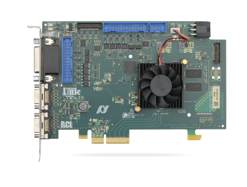
抓取鏈雙重
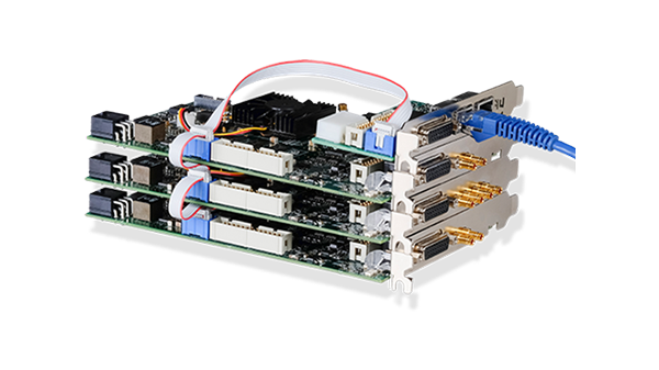
適用於單一完整配置或雙基礎配置 Camera Link 攝影機的影像擷取卡
- 適用於兩台獨立的 Camera Link Base 配置相機
- 適用於一台 Camera Link Base、Medium、Full、72-bit 或 80-bit 相機
- 直接相容於市面上數百款 Camera Link 相機
- PoCL(Camera Link供電技術)
- ECCO:延長Camera Link線纜長度
- PCIe Gen 2 x4匯流排
- 具備20條功能豐富的數位輸入輸出線
- 支援通用控制協定(GenCP)
- 相容於eGrabber驅動程式
- 相容於Memento事件記錄工具
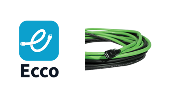
ECCO:擴展相機鏈纜線操作
使用更長的 Camera Link 線纜,長度可達 15 公尺!
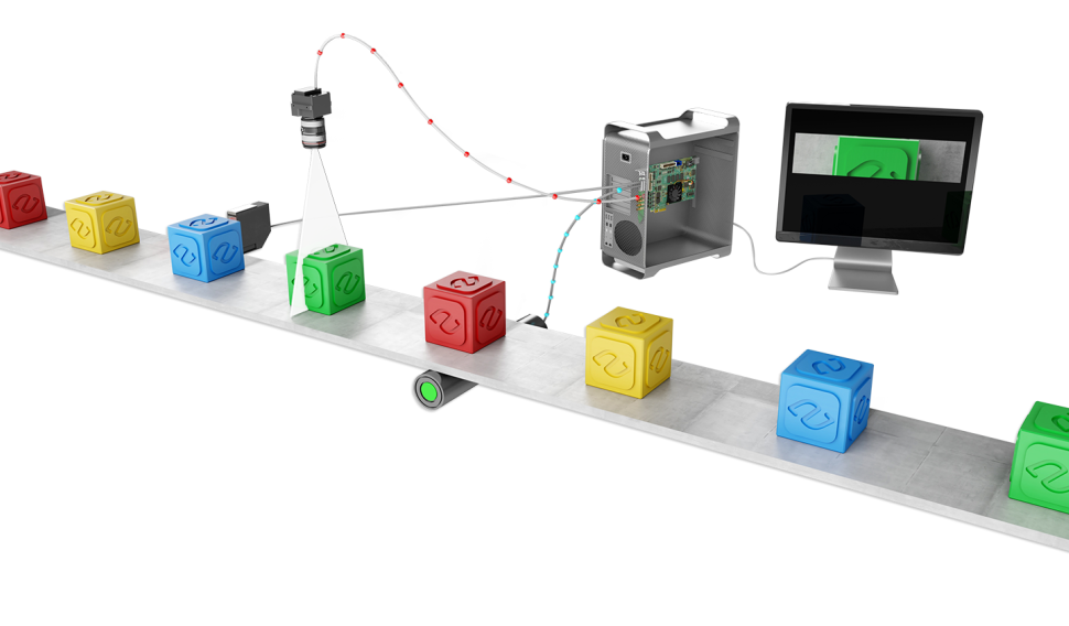
線掃描觸發功能
Allied Vision影像擷取卡具備多種功能,可同步線掃描或1D相機、感測器及照明控制器。影像擷取卡能根據運動編碼器傳送的訊號,控制相機掃描速率。
其支援連續卷材掃描(可檢測無限延續的連續移動表面,絕不遺漏任何掃描線)與離散物件掃描(用於擷取在相機前方移動的物件影像)。
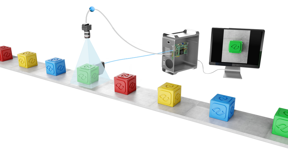
區域掃描觸發功能
Allied Vision影像擷取卡具備多種功能,可同步區域掃描或2D相機、感測器與照明控制器,適用於視野範圍內的靜止或移動物體,亦適用於移動式相機。
效益
相容於 eGrabber
-
-
eGrabber Studio:eGrabber 的互動式評估和演示應用程序,可存取 GenTL Producers 公開的 GenICam 功能。
-
GenTL Console:一個命令列工具,可存取 Euresys GenTL Producers 公開的功能和命令。
-
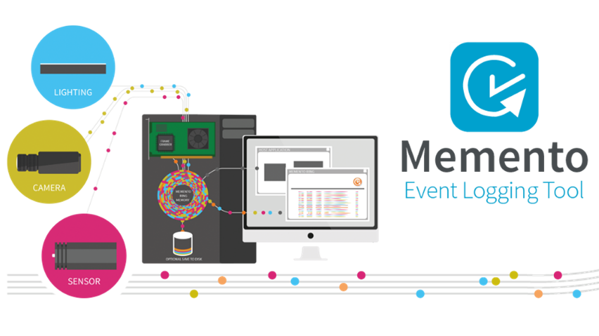
Memento 事件記錄工具
-
- Memento 是一款適用於 Coaxlink 與 Grablink 擷取卡的高階開發與除錯工具。
- Memento 會精確記錄所有與攝影機、擷取卡及其驅動程式以及應用程式相關的事件日誌。
- 它為開發人員提供精確的時間軸事件記錄,包含時間戳記、上下文資訊及邏輯分析器檢視。
- 無論在應用程式開發、除錯階段或機器運作期間,皆能提供極具價值的輔助功能。
C2C-Link 攝影機同步
允許精確同步多個連接至同一張卡的區域掃描或線掃描相機
-
- 至同一張卡
- 與同一台電腦中的不同卡
- 至不同電腦中的不同卡

高效能 DMA(直接記憶體存取)
-
- 直接轉移至使用者分配的記憶體
- 硬體散射-聚合支援
Windows、Linux 與 macOS 驅動程式皆可使用
包含對 Intel 64 位元平台以及 ARM 64 位元平台的支援。
通用輸入輸出線
-
- 相容於多種感測器與運動編碼器。
- 高速差動輸入:支援最高 5 MHz 的正交運動編碼器。
- 隔離式電流感測輸入:支援 5V、12V、24V 信號電壓,最高 50 kHz,個別電氣隔離能力達 250VDC 及 170VAC 有效值。
- 隔離式接觸輸出。
- 高速 5V 相容 TTL 輸入/ LVTTL 輸出。
靈活的線掃描相機操作與速率轉換器
-
- 速率轉換器是一款智慧型、可編程的頻率倍增器/分頻器。
- 搭配運動編碼器與線掃描相機使用時,可讓使用者選擇影像中像素的長寬比例。
- 它提供了一種校準擷取鏈的方法,可輕鬆實現正方形(1:1 寬高比)像素。
線掃描元數據插入
啟用此功能時,系統將同步記錄影像資料外的元數據。每擷取一條影像線時,皆會捕捉該線的元數據;而緩衝區元數據僅在擷取緩衝區首條影像線時進行捕捉。元數據由可配置的通用事件計數器、正交編碼器位置計數器及/或I/O線狀態組合而成。此功能使線掃描應用能將影像資料與系統事件(包括運動編碼器位置)建立關聯。
eGrabber
探索我們的影像擷取卡軟體

General
| Product name: | PC1628 Grablink Duo |
| Product code: | 1628 |
| Product status: | Released |
Mechanical
| Form factor: | PCIe Card |
| Cooling method: | Air cooling / fan-cooled |
Host Bus
| Standard: | PCIe 1.0 |
Camera Inputs
| Camera interface standard: | Camera Link |